


QX-Motor
JP Hobby Multifunction Combined Controller V1/V2 for ER05/ ER08/ ER10/ ER120/ ER150/ ER200 Electric Landing Gear
JP Hobby Multifunction Combined Controller V1/V2 for ER05/ ER08/ ER10/ ER120/ ER150/ ER200 Electric Landing Gear
Couldn't load pickup availability
JP Hobby Multifunction Combined Controller V1/V2 for ER05/ ER08/ ER10/ ER120/ ER150/ ER200 Electric Landing Gear
Description
The main difference between the new Combined Retract Controller and the Integrated Retract Controller is that the Combined Retract Controller features three gear door channels, allows the setting of both V1 and V2 versions, and offers the ability to change the direction of the gear door servo.
Additionally, it supports all versions of the ER-005, ER-010, ER-120, ER-150, and ER-200 retract systems, automatically identifying the specific requirements of the landing gear.
-
The functions of the JP Hobby module are multiple:
-
Automatic detection of the supply voltage
-
Adjusting the supply voltage of the servos actuating the gear doors
-
Adjusting the direction of rotation of the servos actuating the gear doors
-
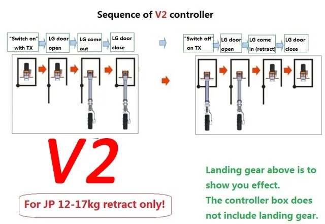
Mode selection:
- 1: Opened gear doors when the landing gear is out
- 2: Closed gear doors when the landing gear is out
Specifications
-
Dimensions: 52x37x14mm
-
Entraxe: 64mm
-
Voltage range: 7.4-8.4V
-
Weight: 34.7g
Gear Door Controller Setup Instructions
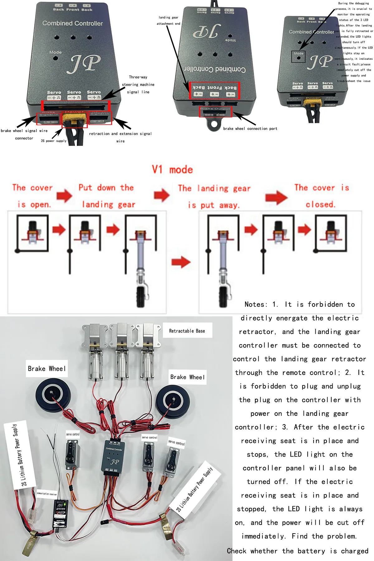
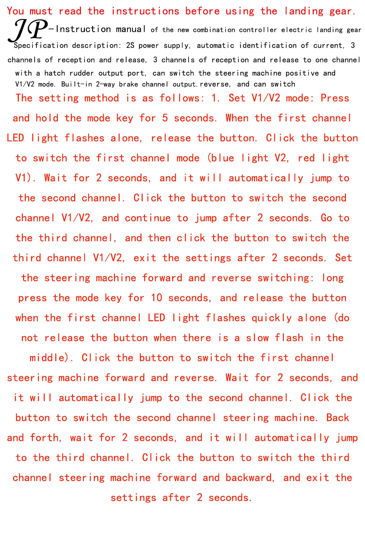
This controller supports three gear door channels, each of which can be configured independently. You can adjust V1/V2 positions and servo directions (positive or negative) for each gear door.
Function 1: V1/V2 Position Setup
(V1: landing gears doors stay open - V2 : closed)
To enter the position setup mode:
1.Press and hold the Mode key for 5 seconds.
2. The red light in dicates the controller is in V1 set up mode.
3. Press the Modekey again to switch to V2 mode, indicated by ablue light.
If the Mode key is not pressed with in a few seconds, the controller will automatically move to the next channel.
Once all three channels have been configured, the system will automatically exit the setup mode.
Function 2: Servo Direction Setup
To configure the servo direction (positive or negative):
1.Press and hold the Mode key for 10 secondsto enter servo direction setup mode.
2. A red light in dicates the positive direction, and a blue light in dicates the negative direction.
(Note: In some models, this color assignment may be reversed.)
If the Mode key is not pressed, the system will automatically proceed to the next channel.
After all three channels have been set, the system will exit the setup mode automatically.


Materials
Materials
Shipping & Returns
Shipping & Returns
Dimensions
Dimensions
Care Instructions
Care Instructions


-
Free Shipping
Pair text with an image to focus on your chosen product, collection, or blog post. Add details on availability, style, or even provide a review.
-
Hassle-Free Exchanges
Pair text with an image to focus on your chosen product, collection, or blog post. Add details on availability, style, or even provide a review.